Inventory
List of components available in the lab.
Date: 2022-08-27
| Name | Description | Quantity |
|---|---|---|
STM32G431KBT6 |
Microcontroller, 32-pin |
33 |
STM32G441KBT6 |
Microcontroller, 32-pin |
33 |
STM32G441CBT6 |
Microcontroller, 48-pin |
20 |
10118193-0001LF |
Micro USB socket |
100 |
CM1223-02SO |
TVS diodes 2-ch |
57 |
BUK6Y10-30PX |
PFET SOT669 |
20 |
BUK6Y24-40PX |
PFET SOT669 |
30 |
NCP718BSN500T1G |
LDO 5V 300mA |
40 |
NCV8730ASN500T1G |
LDO 5V 150mA |
24 |
NCP164CSN330T1G |
LDO 3.3V 300mA |
63 |
XTPS62933DRLR |
TPS62933 buck converter |
50 |
SRP6060FA-5R6M |
Inductor 5.6uH 10A |
20 |
FTSH-105-01-L-DV-K |
Programmer connector |
18 |
MAX14930DASE+ |
4-ch isolator |
27 |
MAX12930EASA+ |
2-ch isolator |
16 |
PDRV8243HRXYQ1 |
DRV8243 motor driver |
36 |
Motor driver
Requirements
-
Should be capable of driving robot’s motors: https://www.pololu.com/product/4751
-
Brushed motor with quadrature encoder
-
Rated voltage: 12V
-
Stall current at 12V: 5.5A
-
Maximum (continuous) power: 12W
-
-
Maximum voltage from 4S battery is 16.8V (4x 4.2V).
-
Driver does not need to be capable of driving the motor at stall current. Driving the motor at stall current for longer period will overheat the motor.
-
Motor’s power can be higher than the rated power for a short duration.
-
Driver should be capable of limiting the current somewhere between the stall current and maximum power limit (where current is 12W / 16.8V).
Recommended
DRV8243
-
Product code: PDRV8243HRXYQ1 (HW variant, pre-production)
-
Package: VQFN-HR (14)
-
Datasheet 2021-08 (contains pre-production version information)
Microcontroller
Requirements
-
Should have enough timers:
-
For generating PWM signals for drivers. Typically, brushed motor drivers have 1 or 2 PWM inputs.
-
For reading encoders outputs in encoder mode. Encoders can be read with external interrupts, but using timer’s encoder mode avoids the overhead of handling the interrupts.
-
For generating PWM signal for thrower motor driver. Thrower’s brushless motor is driven by low cost ESC (electronic speed controller), that has 1 PWM signal input. This PWM signal should be generated by a separate timer to be able to use different PWM frequency, since all PWM outputs from a timer have same the frequency.
-
If servo motors are needed for the thrower, then additional PWM output is needed for each servo.
-
Additional timer is needed to generate periodic interrupts for motor control code in the firmware.
-
-
Should have USB interface or UART/USART interface if USB-UART bridge is used.
Recommended
STM32G441KB
USB connector
-
For powering the microcontroller and for communicating with robot’s computer.
-
Micro USB Type B is commonly used.
Recommended
Amphenol 10118193-0001LF
USB protection
Requirements
-
TVS diodes compatible with USB voltages and signal speeds.
Recommended
CM1223-02SO TVS diode array
-
Package: SOT23−5
Voltage regulators
Recommended
SOT23-5 package with following pinout:
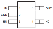
There are no other good reasons to use this pinout, other than that it has been used on previous boards.
It’s fine to use other packages that have a thermal pad or in general better thermal performance. Thermal performance of SOT23 package is relatively poor, but good enough for low currents.
Recommended voltage regulators below are just some that meet the requirements. There are probably cheaper and better performing regulators available.
Voltage regulator for microcontroller
Requirements
-
Input: 5V from USB.
-
Output: 3.3V, >200mA
-
For powering the microcontroller, encoders, isolators.
Recommended
NCP164CSN330T1G
-
Package: TSOP-5
Voltage regulator at the motor driver’s side
Requirements
-
Input: 4S battery voltage (up to 16.8V).
-
Output: 5V, >50mA
-
For powering the isolators, driver pullup resistors.
Recommended
NCV8730ASN500T1G
-
Package: TSOP-5
Isolators
Requirements
-
Should electrically isolate motors' battery from computer’s battery to avoid short circuits on the motor’s side damaging the computer.
-
Signals between the microcontroller and motor drivers should go through isolator(s).
-
Needs to work with 3.3V and 5V.
Recommended
MAX14930DASE+
-
4 channels
-
2 isolators can be used for 3 pairs of motor driver signals, 1 thrower PWM signal and optionally for 1 thrower servo signal.
-
SOIC16 package
MAX12930EASA+
-
2 channels
-
Optional component when additional signals need to be isolated.
-
SOIC8 package
Encoder connectors
Requirements
-
For connecting encoder power and signal wires to the microcontroller.
-
4 wires for each encoder.
Recommended
Micro-MaTch 215079-4
Thrower ESC connector
Requirements
-
For connecting thrower motor controller.
-
Only 2 wires (GND and PWM) are needed.
Recommended
Micro-MaTch 215079-4
Programmer connector
Requirements
-
For connecting STLink programmer to the microcontroller.
Recommended
Samtec FTSH-105-01-L-DV-K
Reverse voltage protection
Requirements
-
For avoiding reverse voltage damaging the components.
-
Should be connected between positive supply instead of ground to avoid having different ground potentials.
-
Simple and efficient solution is to use P-channel MOSFET.
-
MOSFET’s drain-source and gate-source rated voltages should be higher than battery voltage.
-
If battery voltage is higher than gate-source voltage, then zener diode can be used to clamp the gate voltage, and a resistor can be used to limit current through zener diode.
-
Recommended
BUK6Y10-30P
High current connections
Requirements
-
For connecting power input from battery and outputs from motor drivers.
Recommended
-
No separate components are needed.
-
Simple rectangular SMD pads, where wires can be soldered, take little room and creates a reliable connection.
-
Pad size can be 3 x 3 mm or larger for 18 AWG wire.
LEDs
Requirements
-
LEDs can be connected to microcontroller and used in firmware to indicate that something is working.
-
LEDs can also be connected to voltage regulator output to indicate that the board has power.
-
LED’s brightness is controlled with current. The simplest way to limit current is to use resistor in series with the LED.
-
LED’s current can be calculated with the following equation: \$I = (V_(s\upply) - V_F) / R\$ , where VF is LED’s forward voltage. VF can be found in the LED’s datasheet.
Recommended
-
0603 SMD package.
-
Current around 1 mA. Higher currents usually make the LED too bright and waste energy. Exact current is not that important if LED is used for visual indication and can be changed later by replacing the resistor.