Software and documentation
This guide assumes that STM32CubeIDE and HAL libraries are used.
Programmer interface
Programmer interface can be enabled from SYS → Debug: Serial Wire.
GPIO
Output
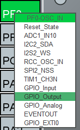
Pin can be changed to GPIO_Output in the Pinout view by left clicking on the pin.
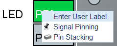
Label can be added by right clicking on the pin and selecting Enter User Label.
Pin output state can be changed with HAL_GPIO functions.
HAL_GPIO_TogglePin(LED_GPIO_Port, LED_Pin);USB
USB virtual serial port can be used to communicate with robot’s computer.
Enable by checking USB → Device (FS) and selecting USB_DEVICE → Class For FS IP: Communication Device Class (Virtual Port Com).
One option to implement USB communication is to send binary data that is defined by structs. Binary communication is easier to implement and computationally more efficient than text based communication.
/* USER CODE BEGIN EXPORTED_FUNCTIONS */
void CDC_On_Receive(uint8_t* buffer, uint32_t* length); // (1)
/* USER CODE END EXPORTED_FUNCTIONS */-
Declare a function to be called when data is received from USB.
static int8_t CDC_Receive_FS(uint8_t* Buf, uint32_t *Len)
{
  /* USER CODE BEGIN 6 */
  CDC_On_Receive(Buf, Len); // (1)
  USBD_CDC_SetRxBuffer(&hUsbDeviceFS, &Buf[0]);
  USBD_CDC_ReceivePacket(&hUsbDeviceFS);
  return (USBD_OK);
  /* USER CODE END 6 */
}-
Add call to the function in CDC_Receive_FS and pass pointers to data and length of data. CDC_Receive_FS is a handler for incoming USB data.
/* USER CODE BEGIN Includes */
#include "usbd_cdc_if.h" // (1)-
Include usbd_cdc_if.h, where the CDC_On_Receive function was declared.
/* USER CODE BEGIN 0 */
typedef struct Command { // (1)
  int16_t speed1;
  int16_t speed2;
  int16_t speed3;
  uint16_t throwerSpeed;
  uint16_t delimiter; // (2)
} Command;

typedef struct Feedback { // (3)
  int16_t speed1;
  int16_t speed2;
  int16_t speed3;
  uint16_t delimiter;
} Feedback;

Command command = {.speed1 = 0, .speed2 = 0, .speed3 = 0, .throwerSpeed = 0, .delimiter = 0}; // (4)
volatile uint8_t isCommandReceived = 0; // (5)

void CDC_On_Receive(uint8_t* buffer, uint32_t* length) { // (6)
  if (*length == sizeof(Command)) { // (7)
    memcpy(&command, buffer, sizeof(Command)); // (8)

    if (command.delimiter == 0xAAAA) { // (9)
      isCommandReceived = 1;
    }
  }
}
/* USER CODE END 0 */-
Define struct for received data.
-
Delimiter is used as a separator between packets of data. Preferably something that will never appear in the data should be used.
-
Define struct for sending data. This can be omitted if there is no need for data from mainboard.
-
Instance of received data.
-
Boolean (0/1) variable to signify that data has been received. Variable is marked volatile to prevent the compiler from removing it during optimisation.
-
Define the function that is called when data is received. It is usually preferable to keep interrupt handlers small and fast to avoid blocking other code from executing. Only data copying and setting isCommandReceived to 1 is done in the handler. Rest is handled in the main while loop.
-
Check if received data the has same length as Command struct.
-
Copy received data to command instance.
-
Check the delimiter as a validation of received data.
int main(void)
{
  // ...

  /* USER CODE BEGIN 2 */
  Feedback feedback = { // (1)
      .speed1 = 0,
      .speed2 = 0,
      .speed3 = 0,
      .delimiter = 0xAAAA
  };
  /* USER CODE END 2 */

  /* Infinite loop */
  /* USER CODE BEGIN WHILE */
  while (1)
  {
    /* USER CODE END WHILE */

    /* USER CODE BEGIN 3 */
    if (isCommandReceived) { // (2)
      isCommandReceived = 0;
      HAL_GPIO_TogglePin(LED_GPIO_Port, LED_Pin); // (3)

      feedback.speed1 = motor1Control.speed; // (4)
      feedback.speed2 = motor2Control.speed;
      feedback.speed3 = motor3Control.speed;

      CDC_Transmit_FS(&feedback, sizeof(feedback)); // (5)
    }
  }
  /* USER CODE END 3 */
}-
Define an instance of Feedback for sending data.
-
Only return data when something has been received.
-
Toggle LED to indicate that data has been received.
-
Update feedback with current motor speeds.
-
Send data over USB.
Encoders
Motors have quadrature encoders, that output 2 signals that are 90 degrees out of phase depending on the rotation direction. The easiest way to read encoder signals is using timer’s encoder mode. When timer’s encoder mode is used, then PWM outputs can’t be used on the same timer for controlling motor drivers, because timer’s counter value will be changed by encoder signals instead of clock signal.
STM32CubeIDE timer configuration
-
Mode:
-
Combined Channels: Encoder Mode
-
-
Configuration:
-
Parameter settings:
-
Encoder Mode: Encoder Mode TI1 and TI2
This will count all the edges from both of the timer’s inputs.
-
-
Timer code
Encoder can be enabled by calling HAL_TIM_Encoder_Start.
int main(void)
{
  // ...

  /* USER CODE BEGIN 2 */
  HAL_TIM_Encoder_Start(&htim1, TIM_CHANNEL_1 | TIM_CHANNEL_2);
  /* USER CODE END 2 */

  // ...
}
Current encoder value can be read from timer’s counter register. It is useful to have timer’s autoreload register value at 65535, which is the highest 16-bit value and cast encoder value to signed 16-bit integer (int16_t). If all the encoder timers are 32-bit, then it might be more useful to do the same with 32-bit types. Casting to signed integer allows for a simple encoder value change calculation in both negative and positive directions. Encoder value (position) change can be used as a speed feedback in motor control.
int16_t position = (int16_t)TIM1->CNT;
int16_t positionChange = position - positionPrev;
PWM
STM32CubeIDE timer configuration
-
Mode:
-
Channel#: PWM Generation CH#
-
-
Configuration:
-
Parameter settings:
-
Counter settings:
-
Prescaler: see below
-
Counter period: see below
-
-
-
Frequency
Frequency of each timer can be calculated from prescaler register value (PSC) and counter period/autoreload register value (ARR) with a following formula:
\$f = f_(clock) / ((PSC + 1) (AR\R + 1)\$
fclock is the timer clock, that can be found and configured from Clock configuration page in STM32CubeIDE, where it is referred to as APB1 timer clocks or APB2 timer clocks.
To see if timer is connected to APB1 or APB2, refer to Figure 1. STM32G441xB block diagram in the datasheet or 7.4.17 APB1 peripheral clock enable register 1 (RCC_APB1ENR1) and 7.4.19 APB2 peripheral clock enable register (RCC_APB2ENR) in the reference manual.
All PWM outputs of a timer share the same frequency.
PWM for wheel motor drivers
Each motor driver needs 2 PWM inputs or 1 PWM and 1 direction input. Recommended way for pre-production DRV8243 motor drivers is to use 1 PWM and 1 direction input.
If PSC = 0, ARR = 65535, fclock = 160 MHz, then fPWM ≈ 2448 Hz, which is suitable frequency for motor drivers.
PWM for thrower motor driver
Usually brushless ESCs are controlled by single PWM signal with frequency of 50 Hz (period = 20 ms) and pulse width between 1 ms and 2 ms. Often higher frequencies and shorter pulse width are supported.
Newer ESCs also support DShot protocol, which is a digital protocol as opposed to regular PWM being analog.
DShot can be implemented with 1 PWM output and DMA.
Timer for thrower motor PWM should be separate from wheel motor PWM timers to be able to use different frequency.
PWM code
PWM can be enabled by calling HAL_TIM_PWM_Start.
int main(void)
{
  // ...

  /* USER CODE BEGIN 2 */
  HAL_TIM_PWM_Start(&htim2, TIM_CHANNEL_1);
  /* USER CODE END 2 */

  // ...
}
PWM duty cycle can be changed by writing to timer’s capture/compare register. Duty cycle can range from 0 to the value specified in autoreload register.
TIM2->CCR1 = 9500; // Timer 2, channel 1Motor control
Periodic interrupt
Using fixed period for calculations simplifies motor control by allowing to omit time from calculations.
Timer can be used to generate periodic interrupts. Calculations can be done in interrupt handler.
Prescaler and autoreload registers need to be configured under Parameter Settings to set the frequency of interrupts. Good frequency could be 100 Hz. Higher frequencies reduce the number of encoder changes between interrupts and lower frequencies reduce the motor control responsiveness.
Timer (global or update) interrupt can be enabled under NVIC Settings. Update interrupt is generated every time the timer’s counter register overflows from autoreload register value to 0.
Timer can be enabled by calling HAL_TIM_Base_Start_IT.
// ..
HAL_TIM_Base_Start_IT(&htim6);
/* USER CODE END 2 */
Timer’s update interrupt can be defined by implementing HAL_TIM_PeriodElapsedCallback function from stm32g4xx_hal_tim.c. It is usually not recommended to have long-running code in interrupt handler, but since motor control code is time sensitive (by omitting time from calculations) and there is no other computation done at the same time, it is fine to have it in interrupt handler.
void HAL_TIM_PeriodElapsedCallback(TIM_HandleTypeDef *htim) {
  // Motor control calculations can be called from here
}
PID controller
Motor speed control can be implemented with a PID controller. Just a PI controller, where derivative part is not implemented/used, is usually also fine when controlling motor speed.
Encoder changes can be used as a speed feedback. Setpoints can be received through the USB communication. Output of the controller should be PWM for a motor driver.
Boot configuration
Boot configuration is detailed in reference manual under 2.6 Boot configuration section.
nSWBOOT0 bit in FLASH_OPTR registry determines whether BOOT0 pin (when nSWBOOT0 = 1) or nBOOT0 in FLASH_OPTR registry (when nSWBOOT0 = 0) is used to select boot mode.
BOOT0 can be left unused or used for some other function if nSWBOOT0 is set to 1 in FLASH_OPTR registry.
One option to check and change FLASH_OPTR registry settings is to use STM32CubeProgrammer and Option Bytes in there.