Intro
To mill out your parts from plastic sheet, we need to generate G-code for the milling machine. This can be achieved with Fusion’s MANUFACTURE feature. This document describes most important properties and methods how to prepare your designs for milling.
Starting
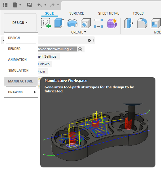
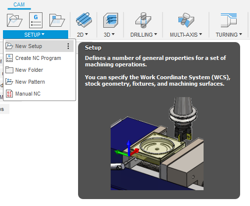
To start creating a CAM (computer-aided manufacturing) job for your design, you should select MANUFACTURE from left upper menu.
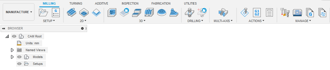
Now you should see new toolbar with different CAM related tools:
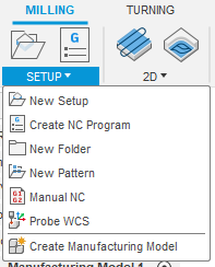
Create a Manufacturing Model (MILLING → SETUP → Create Manufacturing Model) to make a model that you can edit without affecting the original model.
If you have a multipart assembly you can use the "Arrange" functionality from Fusion 360 preview features to automatically arrange and flatten the assembly.
A video tutorial on how to enable and use the "Arrange" functionality can be found here:
https://youtu.be/7egLufCg5tk
Job setup
First thing to do is to create a new setup for your job. For this, choose SETUP → New Setup from toolbar.
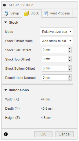
You should now set stock properties and origin point (the point where the milling starts). Usually the starting (work zero) point should be in the bottom left corner of your part on top of the stock. Z axis should point up, X and Y axis should point along the sides of your part. Correct orientation can be chosen by selecting relevant properties under Work Coordinate System (WCS). Depending on how the design is oriented, you might need to select different options.
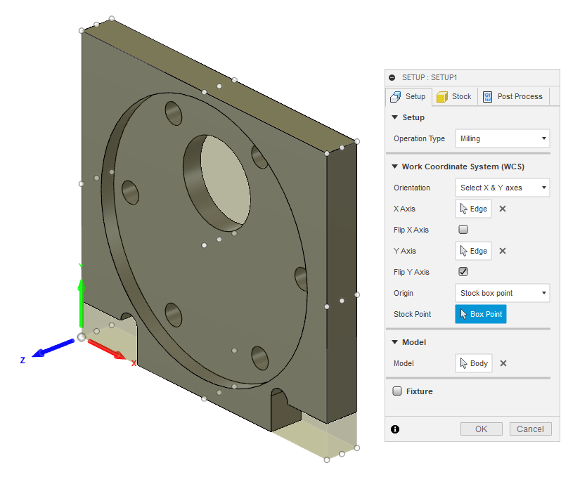
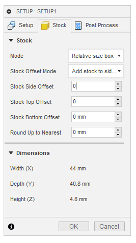
Another important thing here is to set stock offsets to 0 on the Stock tab.
Now you can click OK, and you have created your first setup for milling job.
Drilling
Drilling should usually be the first operation. This can reduce toolchanges, since other operations are done with milling bits.
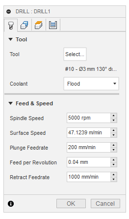
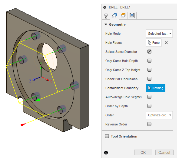
Create new drilling operations from the toolbar DRILLING → Drill.
Select or create a tool. Change the Spindle Speed and Plunge Feedrate if necessary. Refer to the tools table below.
Select the face of one of the holes. Same size holes can be included by selecting Select Same Diameter.
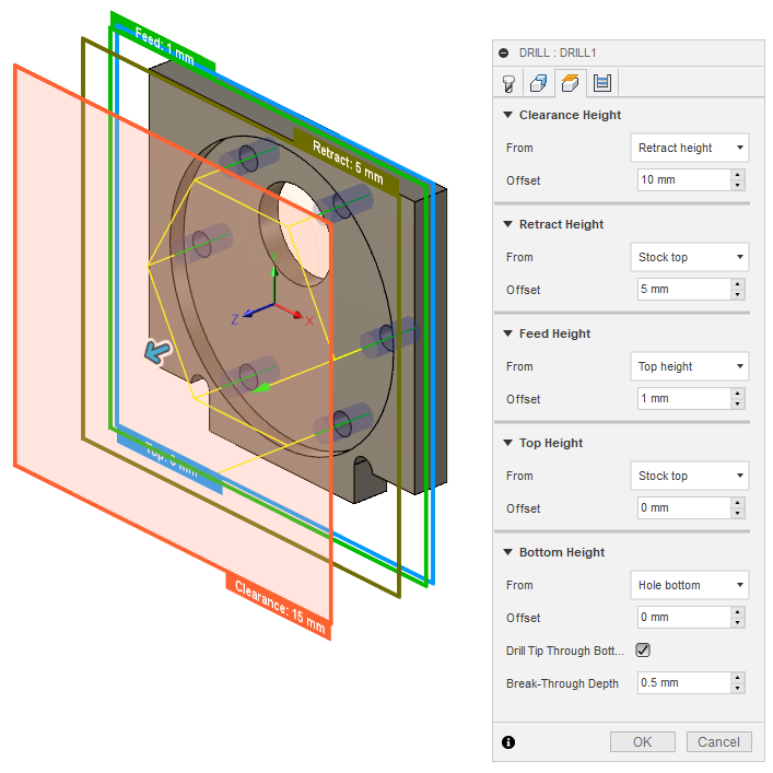
On the heights tab, change the Feed Height Offset to 1mm. This helps to save time since drilling does a lot of movements in z-axis direction and (plunge) feedrate is rather slow.
If the drilled holes do not start from the top of the remaining stock, change Top Height From to Stock top. Otherwise the drill will be plunged too fast into the uncut material.
Select Drill Tip Through Bottom and add small Break-Through Depth, if drilling all the way through the material.
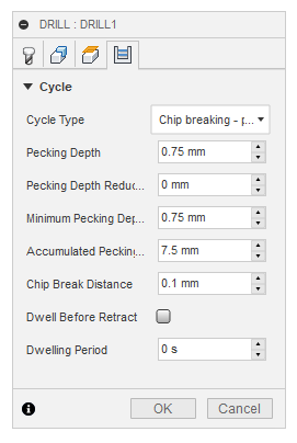
On the Cycle tab select Cycle Type to be Chip breaking - partial retract or Deep drilling - full retract. Those types help to avoid plastic from getting stuck in the hole and starting to melt.
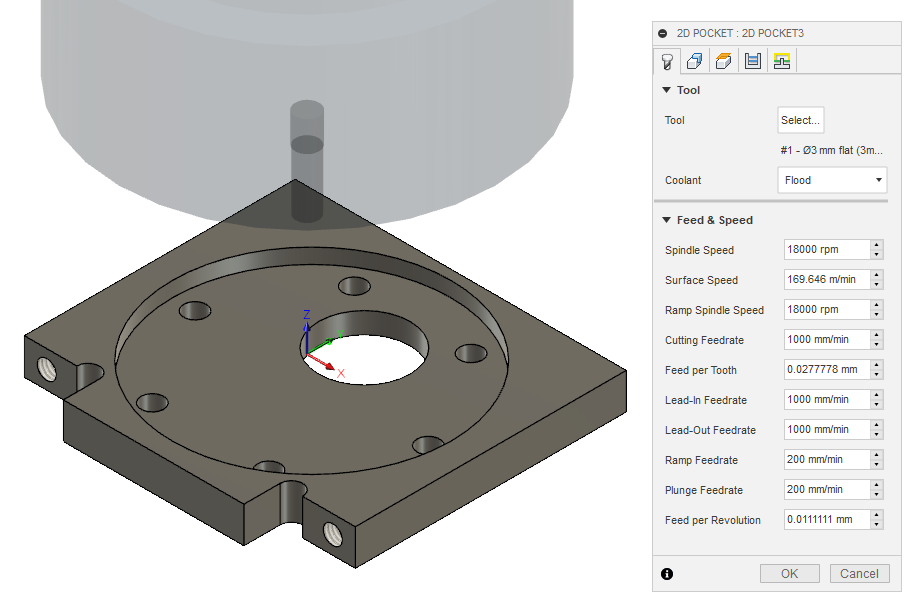
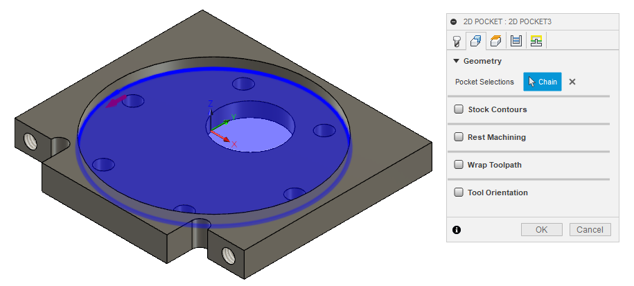
Pocket operation can be used when you need to mill something that does not go all the way through the material.
If you need to cut all the way through, then prefer 2D contour operation. Contours do not cut all the material inside a profile and take less time because of that.
First select a flat end mill as the cutting tool and adjust the speeds and feeds if necessary.
Select bottom edge for Pocket Selection.
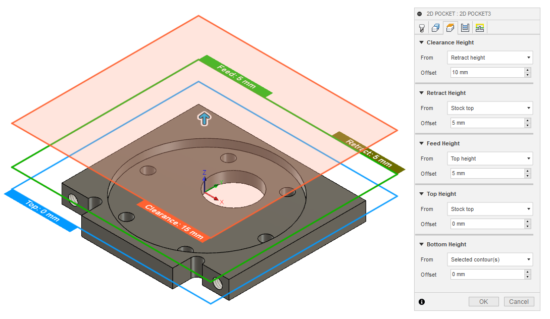
Heights can be usually left unchanged.
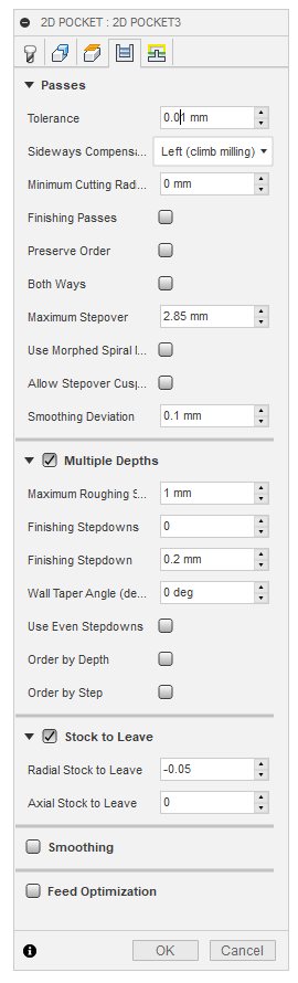
On the Passes tab, change Tolerance to 0.01, if not using finishing passes.
Select Multiple Depths. Default value of 1 mm works well for Maximum Roughing Stepdown. Cutting too much material in one pass can result in bad surface finish or the tool can break under load.
Uncheck Stock to Leave or use small negative Radial Stock to Leave if you need looser fit.
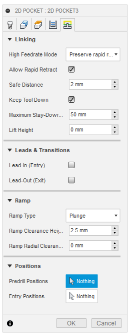
On the Linking tab, uncheck Lead-In (Entry) and Lead-Out (Exit). Change Ramp Type to Plunge. Plastic is soft enough to not require more gradual ramping.
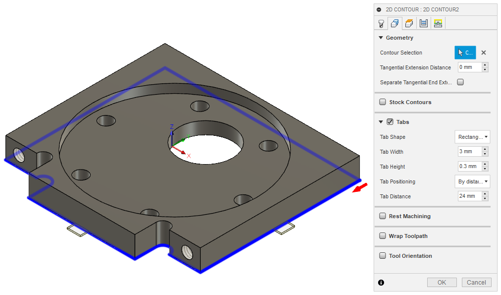
2D contours
Use contour operation if you need to cut all the way through the material, you need to remove some material from the edge of the existing part, or you need to cut a something that has the same width as the tool. Although you should probably use slot operation for the latter case.
Most of the same settings apply to the contour operation as for the pocket operation.
When selecting the contour edge make sure that the arrow is outside the part. The arrow shows the side of the cut. To change the side, click on the arrow.
For outer or larger inside contours select Tabs from Geometry settings. Tabs help to keep the parts in place. Loose parts can get in the way of the tool, which can damage the parts and break the tool. Tabs are usually not needed for small inside contours.
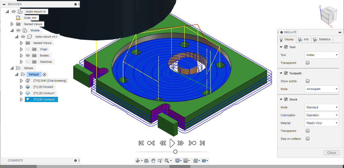
Checking the results
Now that you have created your CAM job, you can quickly check it for any obvious mistakes. Simulating helps with that. Not only does it tell you, how long the job will take, but allows you to see exactly how it will start to cut the material. Simulation can be opened from right click menu of the setup or operation(s).
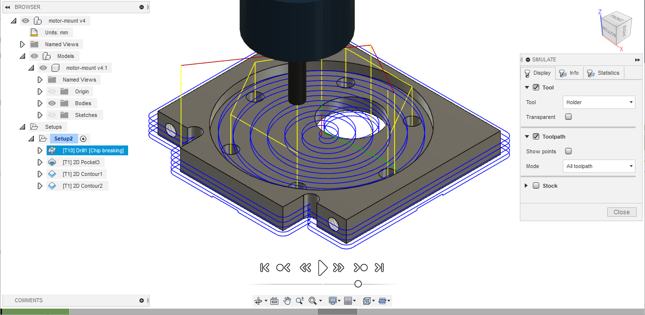
Turn on Stock and go to the end of the simulation to find any unexpected or missing cuts. The yellow and red lines are movement and blue lines are the cutting paths.
If there are any unexpected cuts being made with non-blue line, then try to uncheck Keep Tool Down in the operation settings on the Linking tab.
Post process
Post processing turns the operations into G-code. G-code is used to control the milling machine.
Setting up
-
Search "STEPCRAFT UCCNC"
-
Click "Download" and put the downloaded file in Posts folder (C:\Users\<USERNAME>\AppData\Roaming\Autodesk\Fusion 360 CAM\Posts)
First time usage
-
Open MANUFACTURE in Fusion 360.
-
Select Post process from Toolbar → Actions or by right-clicking on a setup or operation(s).
-
Click on Setup and choose Use Personal Post Library.
-
Make sure that STEPCRAFT UCCNC is selected under Post Configuration.
-
Uncheck Open NC file in editor.
-
Press Post and save the file.
Usage
-
Open MANUFACTURE in Fusion 360.
-
Select Post process from Toolbar → Actions or by right-clicking on a setup or operation(s).
-
If you want to include all the operations, select the setup. If you want to include only some of the operations, select only those operations.
-
-
Press Post and save the file.
-
Collect your post process files on USB flash drive.
Tool settings
Fusion 360 DigiLab tools library
You can import the file below into Fusion 360.
Material: Polycarbonate
Plastics work better with higher feedrates. At low feedrates the material might start to melt from excessive heat generated by the tool spending too much time in one place.
Following settings are good starting points that have been used before. Reduce feedrates by around half for smaller features like inner contours.
Tools available in DigiLab as of 2019-09-16:
End mills:
| Diameter [mm] | Flute count | End type | Spiral type | Flute length [mm] | Shoulder length [mm] | Overall length [mm] | Shaft diameter [mm] | Link | Cutting feedrate [mm/min] | Plunge feedrate [mm/min] | Spindle speed [rpm] |
|---|---|---|---|---|---|---|---|---|---|---|---|
3 |
2 |
Flat |
Upcut |
6.8 |
8 |
38 |
3.175 |
https://www.sorotec.de/shop/End-Mill-Double-Flute--Flat---3-0mm.html |
1000 |
200 |
18000 |
2.5 |
2 |
Upcut |
3.175 |
https://www.sorotec.de/shop/End-Mill-Double-Flute--Flat---2-5mm.html |
800 |
200 |
18000 |
||||
2 |
2 |
Upcut |
3.175 |
https://www.sorotec.de/shop/End-Mill-Double-Flute--Flat---2-0mm.html |
600 |
200 |
18000 |
||||
1.5 |
2 |
Upcut |
3.175 |
https://www.sorotec.de/shop/End-Mill-Double-Flute--Flat---1-5mm.html |
400 |
200 |
18000 |
Drills:
| Diameter [mm] | Tip angle | Flute length [mm] | Overall length [mm] | Shaft diameter [mm] | Link | Plunge feedrate [mm/min] | Spindle speed [rpm] |
|---|---|---|---|---|---|---|---|
3 |
130 |
10.5 |
38 |
3.175 |
https://www.sorotec.de/shop/Cutting-Tools/sorotec-tools/1-8-tools/Drills/Drills-023175/ |
200 |
5000 |
2.5 |
130 |
10.5 |
38 |
3.175 |
https://www.sorotec.de/shop/Cutting-Tools/sorotec-tools/1-8-tools/Drills/Drills-023175/ |
200 |
5000 |
2.1 |
130 |
10.5 |
38 |
3.175 |
https://www.sorotec.de/shop/Cutting-Tools/sorotec-tools/1-8-tools/Drills/Drills-023175/ |
200 |
5000 |
2 |
130 |
10.5 |
38 |
3.175 |
https://www.sorotec.de/shop/Cutting-Tools/sorotec-tools/1-8-tools/Drills/Drills-023175/ |
200 |
5000 |
1.6 |
130 |
10.5 |
38 |
3.175 |
https://www.sorotec.de/shop/Cutting-Tools/sorotec-tools/1-8-tools/Drills/Drills-023175/ |
200 |
5000 |
Optimizations
Order of operation
Generally move from inside the part to outside. Cutting from outside first can mean that the part comes loose and the inside features can’t be cut.
Example order:
-
Drilling
-
Pockets
-
Inside contours
-
Outside contours
Tool size
Largest available diameter tool size should be used based on smallest inner radius of the milled parts. Larger diameter tools are more rigid and can remove more material in the same time.
Machining time
-
Check machining time from right click menu on setup or operation.
-
Try to avoid cutting too much material.
-
Cutting large pockets with a small tool can take a lot of time.
-
-
Try to reduce part count and complexity.
-
Reduce the Feed height for operations that use a lot of z-axis movements, like drilling.
-
Using the least amount of different tools allows to save time by avoiding tool changes.
-
One option is to design inner radiuses to be as large as possible to avoid using smaller diameter tools.
-
-
If different tools have to be used then it is recommended to order the operations by grouping together those that use the same tool.
Multiple designs with single job
If same thickness material is used for different designs or same design needs to milled out multiple times, then it is possible to save time by creating an assembly from those designs and single CAM job for the entire assembly. Parts should be placed flat next to each other with enough space between them, so that tool used for outer contour fits between them. For example when using 3 mm endmill, there should be at least 3 mm of space between parts to avoid cutting into the part next to the one being milled.
Use joints to place the parts in the assembly. Parts should be on the same plane.
Inspect stock height from setup’s settings. If all the parts have the same thickness, then stock height should not be larger than thickness of the parts.