Reference designators
Reference designators are unique identifiers for each component. For example U1, R2, D2. Designators are usually prefixed with a letter or letters, that correspond to component’s type. Prefix is followed by a number, so that the letter and number combination is unique on the entire schematic. Prefixes can be usually specified in component library.
Common prefixes:
-
U or IC - integrated circuit. For example microcontroller, motor driver or voltage regulator.
-
R - resistor.
-
C - capacitor.
-
D - diode or LED (light emitting diode).
-
LED - light emitting diode.
-
L - inductor.
-
Q - transistor.
-
J or CON - connector.
-
S - switch.
Connections
Labels
Use labels on nets instead of drawing long wires between components.
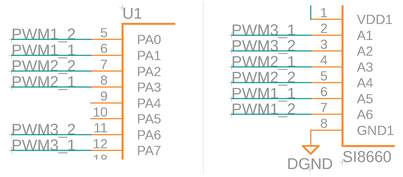
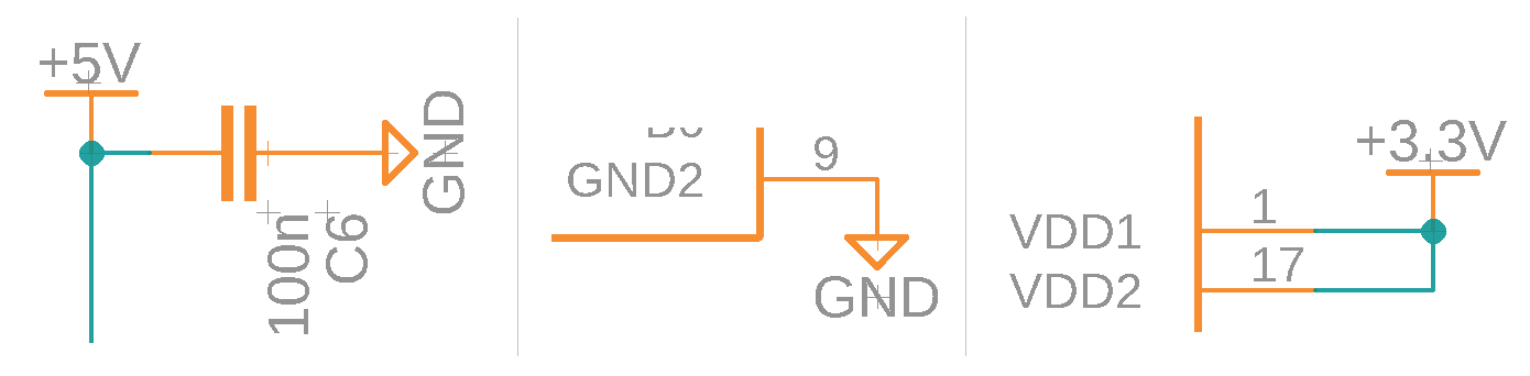
Supply connections
Avoid connecting all the power supply pins together. Use power supply symbols instead.
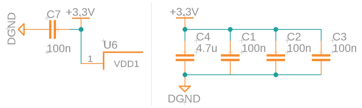
Decoupling capacitors
It is recommended to connect a decoupling (bypass) capacitor close to each power input pin. Common capacitance value is 100 nF. On a schematic, the capacitors can be connected directly to the power pin. Or they can be connected together close to the component when the component has multiple decoupling capacitors and there is not enough room to directly wire them to the component.
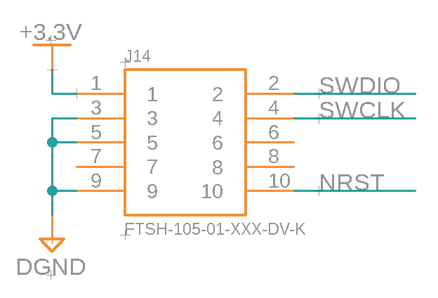
Programmer connector
One place where to find the pinout for programmer connector is in STLINK-V3MINI user manual under 9.1.3 STDC14 for STLINK-V3MINI (STM32 JTAG/SWD and VCP).
On the schematic the connections should look similar to the image below:
Microcontroller
BOOT0 pin
BOOT0 pin can be left unused or used for some other function if nSWBOOT0 is set to 1 in FLASH_OPTR registry. If nSWBOOT0 is set to 0, then pulldown resitor should be connected to BOOT0 pin. For more information see Boot configuration section on Firmware page.
nRESET pin
nRESET pin has an internal pullup. It is recommended to connect 100 nF decoupling capacitor to nRESET pin.
It is possible to connect a switch between nRESET pin and ground to reset the microcontroller manually, but manual reset is usually not needed and can be done by disconnecting the power.
Open drain outputs
nFAULT pin on DRV8243 is an open drain output.
Examples on how to use open drain outputs can be found in this Falstad simulation
Bulk capacitors
Capacitors can be used to avoid voltage dropping too much during fast current consumption increases. Electrolytic or ceramic capacitors or combination of both can be used. Bulk capacitors should be connected between motor driver power input and ground.