Digilab milling
Setup at Delta DigiLab
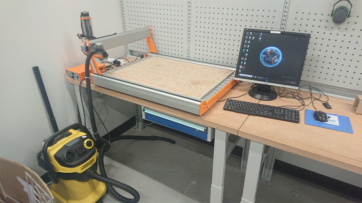
Stepcraft D.840 (D2)

The mill at Delta DigiLab is a Stepcraft D.840 (D2) model. It has a working area of 840 x 600 x 140 mm (L x W x H). The milling spindle used on the mill is an HF-500.
Spindle control unit
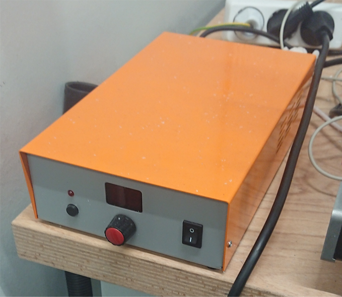
The spindle controller controls the speed of the spindle on the milling motor. The speed values for the spindle are sent to the spindle controller from the computer.
Computer setup
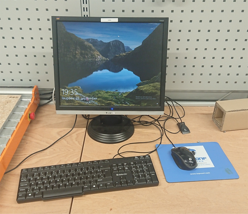
The computer is a NUC attached to the back of a monitor. It is used to control the whole CNC system. A keyboard and mouse are available. There is also a USB extender, through which a flash drive can be connected to the computer. The software used is UCCNC.
Vacuum
The vacuum is used for dust/swarf collection during milling and cleaning after using the CNC. When drilling it’s better to avoid using vacuum and dust collector brush to be able to check if the plastic is starting to melt, which can damage the parts or the drill. During milling, it’s less of a problem because the cutting tool does not stay in the same place for long.
Milling safety
-
Stay alert, watch what you are doing and use common sense when operating the machine.
-
Do not place hands under the spindle or onto the workpiece when the spindle is running.
-
Do not physically force or block any of the axes at any time.
-
Dress yourself properly. Do not wear loose clothing or jewelry. Keep your hair, clothing and gloves away from moving parts so that they cannot be caught.
-
Do wear goggles.
-
Do wear hearing protection when vacuum is in use.
-
Make sure that the workpiece is properly secured.
-
Make sure that the tool is correctly attached to the spindle.
-
Make sure that only the workpiece is on the machine table.
UCCNC
The mill can be controlled through the computer.
UCCNC is the software that will be used to control the machine. It can be launched by the shortcut on the computer’s desktop.
In the image below, different buttons and regions of interest are shown.
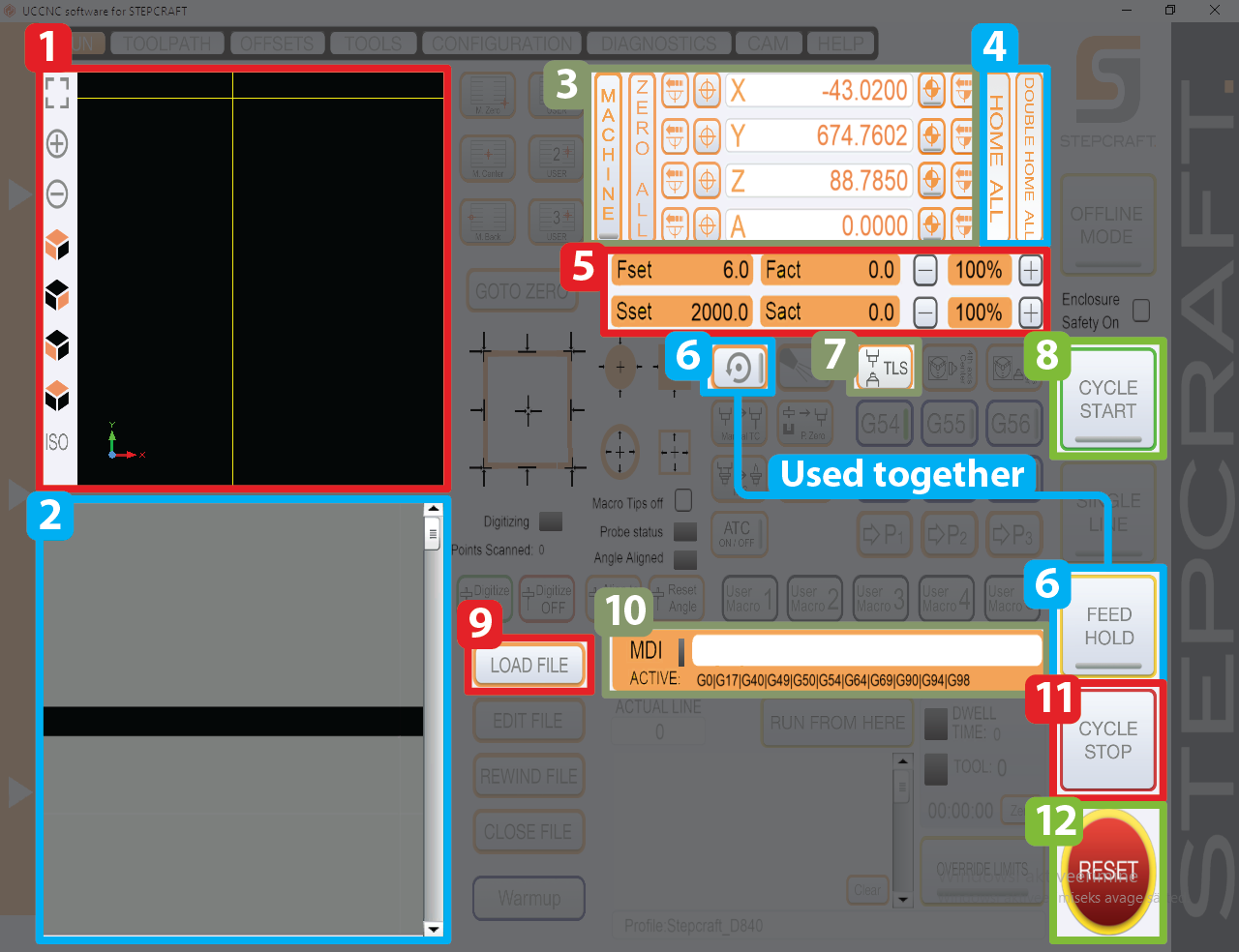
Main view
1 - Tool and toolpath display
This display shows the current position of your tool and the toolpaths of loaded in G-code. The yellow cross shows the current position of your tool. Blue lines are paths which have not yet been processed yet. Yellow lines show paths which have been processed.
The view in the display can be zoomed in and out with the buttons on the left or with the scroll wheel of the mouse. Left-clicking and dragging lets you rotate the view. Right-clicking and dragging lets you pan the view.
2 - G-code display
This display shows the loaded in G-code. The current line that the machine is processing is highlighted during the running cycle.
3 - Current position display
The current position of the tool in all three axis is shown here.
The button MACHINE shows the tool position in absolute (machine) coordinates. A red marking is visible when this option is activated.
The button ZERO ALL will set the workpiece zero point for all axis.
4 - Homing controls
HOME ALL and DOUBLE HOME ALL are used to home the machine.
Homing will move the spindle all the way to one end of the machine, reaching the limits on all axis.
Double homing should always be used, for greater precision. The machine first homes itself, quickly followed by a slower, more precise homing.
5 - Feed and spindle speeds
Feed (F) speed shows how fast the machine moves when cutting.
Fset shows the speed set by the G-code, Fact shows the speed feedback from the axis.
Spindle (S) speed shows the RPM of the spindle.
Sset shows the speed set by the G-code.
Sact receives no feedback from the spindle.
Both the Fset and Sset can be increased/decreased with their corresponding - and + buttons. The value set in the G-code will be multiplied by these values.
Generally, Sset and Fset shouldn’t be randomly adjusted.
6 - Spindle and FEED HOLD
These two buttons are used together if you need to pause during your operation cycle.
IMPORTANT:
FEED HOLD must only be activated when the tool is OUTSIDE or ABOVE the material.
Activating FEED HOLD does not stop the spindle. If FEED HOLD is activated when the tool is inside the material, the tool can keep spinning and melt itself stuck to the material, which can damage the spindle.
IMPORTANT:
Spindle button must only be pressed when pausing the cycle.
Do not press the spindle button at any other time.
7 - Tool Length Sensor (TLS)
The TLS button is used together with the physical Tool Length Sensor to set the height of your tool.
Jogging
Jog panel
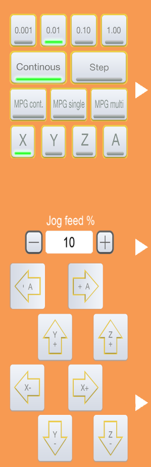
Moving the mouse pointer to the left side of UCCNC will open the jog panel.
Jogging is moving the machine manually outside work processes.
The axis have + and – jog buttons on the jog panel, pressing these buttons, all axis can be jogged to their negative and positive directions.
With Continuous active, the machine axis jogs while the jog button of the axis is being pressed and the jog finishes when the button gets released.
With Step active, the axis moves the selected distance for every jog button presses. Unit lengths moved in Step mode can be selected with the 0.001, 0.01, 0.1 and 1 buttons.
The Jog feed sets the feedrate of the jog movements.
Before milling
-
Inspect the machine.
Check if any of the rail covers are open, if there are any material pieces on the table, if everything looks the way it should. -
Clean the table to remove debris.
You can use a hand brush or the vacuum to clean the table. -
Check for debris in dust collector.
Remove the dust collector brush around the spindle and clean any debris around the spindle collet. -
Disengage the Emergency Stop button.
The mill has no power when the Emergency Stop button is engaged. The button can be disengaged by twisting it clockwise until it pops out. -
Launch UCCNC.
-
Disable Reset in UCCNC.
-
Perform Double-Homing action.
This will move the mill all the way to the end of each axis, calibrating the position of the mill and giving you room to place the workpiece on the table. -
Make sure that the mill can move around in XYZ-axis
The mill should be freely movable around the work area. -
Prepare your material.
Remove plastic coverings off your material and brush over your material to remove debris. -
Place pieces of double-sided tape on the bottom of the material.
Do not remove the coverings off the double-sided tape pieces. The tape should be attached to the extremities (corners and edges) and in the region where your parts will be milled out. Empty regions should also have a few pieces of tape. When placing the tape, make sure that the corners of the tape pieces are not folded. -
Remove the coverings off the double-sided tape.
Lay your material on a flat surface. Remove the coverings off the tape pieces. It’s better to work your way from the back to the front when removing the covering off the tape pieces. -
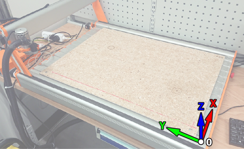
Place your workpiece on the table.
Make sure to properly align the piece. The workpiece must not hang over the table and should be on the spoilboard. A line is drawn on the spoilboard which can be used to align your material. -
Insert your first tool into the spindle.
-
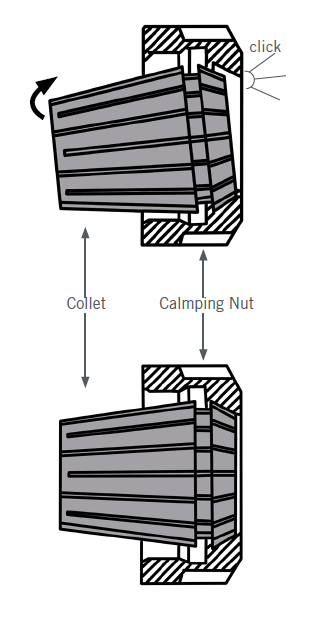
Check that the collet is properly attached to the clamping nut.
-
If the collet is loose, then it should be attached, without a tool inserted, into the clamping nut. An audible click should be heard.
-
-
The tool should be in the collet as deep as possible.
-
If the tool sticks out less, then it will not bend as much.
-
Collet should not cover cutting edges of the tool to avoid damaging them and to avoid blocking chips/swarf during cutting. Leaving about 1-2 mm between the cutting edge and the collet is enough.
-
-
When attaching the tool, the locking button of the spindle has to be pressed in.
-
Screw the clamping nut onto the spindle as much as you can with fingers, then use a 17 mm wrench.
-
Do not attach the collet nut very tightly - when you later have to remove the collet, using too much force can cause you to jerk the machine and the axis can move out of place. Moderate torque should be used to keep the tool attached.
-
-
Zero the X and Y axis.
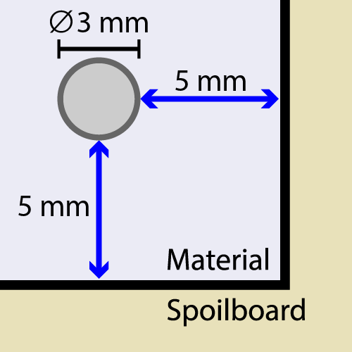
The zero point should be set based on the location of your Work Coordinate System in your CAM. Set the zero point to be about 5 mm from the edges in both X and Y directions towards the inside of the material when a 3 mm diameter tool would be attached to the spindle
-
Check that your G-code fits on the workpiece.
Load in the final outer contour milling G-code and jog over the workpiece with the mill, referencing the screen in UCCNC. Check that when the tool goes over the contour, whether it still stays above the workpiece or it goes too much outside the material. You can repeat the X and Y zeroing if you feel that some edges are too close to the contours. -
Record the absolute X and Y zero positions.
Making sure that the tool is above the workpiece, you can enter the commandG0 X0 Y0into the command line to move the tool to the X and Y zero point. Press the MACHINE button to show the tool position in machine coordinates. Record these numbers (e.g. you can take a picture with your phone). These will help you recover the X and Y position in the case of sudden power loss.DO NOT PERFORM ANY MORE X AND Y ZEROING AFTER THIS.
You will be using the same X and Y zero point for the whole milling process.
Milling
Repeat for each tool until all operations are completed.
-
Zero your tool.
Use the Tool Length Sensor (TLS) to set the Z height of the mill.-
Make sure that the top and bottom of the TLS are free from debris.
-
Place the TLS in a spot where there are no holes and cutouts. Make sure that spot is free from debris.
-
Move your tool above the top of the TLS and press the TLS button in UCCNC to perform the zeroing process.
-
Remove the TLS from the table and make sure that the wire is not on the table and isn’t caught between the Y-axis motors.
-
-
(Only for milling) Attach the brush to the spindle.
The brush attaches magnetically. Make sure that it is properly seated on the spindle. -
(Only for milling) Attach the vacuum to the hose.
Attach the vacuum to the hose that is attached to the spindle. -
Load in the correct G-code.
Load in the G-code that corresponds to the tool in the spindle. -
Turn on the spindle controller.
This will allow to control the spindle. -
Start your operation.
Click CYCLE START to run your G-code. The spindle will spin up and start following the commands in your G-code. -
(Only for milling) Turn on the vacuum.
Max sure to use maximum vacuum power to avoid chips/swarf getting stuck in dust collector. -
Operation finishes.
When the operation finishes, the spindle will spin down and move up from the workpiece. -
Tool change.
Change your tool with the appropriate one for your next operation.
After milling
-
Verify that everything is milled out.
-
Turn off the spindle controller.
-
Move the mill to home position.
This will give you more space to clean the table. -
Remove the tool from the mill.
Attach the collet back onto the spindle. You don’t have to screw it all the way. -
Remove your workpiece from the table.
-
Clean up the machine and surrounding area
Use the vacuum. Clean up the machine, table, walls and floor.