Components
Inventory
List of components available in the lab.
Date: 2024-10-02
| Name | Description | Quantity |
|---|---|---|
STM32G431KBT6 |
Microcontroller |
30 |
STM32G441KBT6 |
Microcontroller |
24 |
STM32G441CBT6 |
Microcontroller |
20 |
DRV8243HQDGQRQ1 |
DRV8243 motor driver |
45 |
10118193-0001LF |
Micro USB socket |
33 |
CM1223-02SO |
TVS diodes 2-ch |
10 |
BUK6Y10-30PX |
PFET SOT669 |
0 |
BUK6Y24-40PX |
PFET SOT669 |
30 |
MIC5504-3.3YM5 |
LDO 3.3V 300mA |
60 |
NCP164CSN330T1G |
LDO 3.3V 300mA |
26 |
NCP718BSN500T1G |
LDO 5V 300mA |
24 |
NCV8730ASN500T1G |
LDO 5V 150mA |
16 |
XTPS62933DRLR |
TPS62933 buck converter |
14 |
SRP6060FA-5R6M |
Inductor 5.6uH 10A |
7 |
FTSH-105-01-L-DV-K |
Programmer connector |
0 |
20021121-00010T4LF |
Pin header, 2x5-pin, 1.27mm pitch, SMD, Vertical, replacement for FTSH-105-01-L-DV-K |
23 |
10129383-906001ALF |
Pin header, 2x3-pin, 2.54mm pitch, SMD, Vertical, for servos |
29 |
SI8640AB-B-IS1 |
4-ch isolator |
0 |
MAX14930DASE+ |
4-ch isolator |
0 |
MAX12930EASA+ |
2-ch isolator |
5 |
RF-WUB190DS-DD |
LED 0603 white |
500 |
RC0603FR-0752K3L |
52.3k 0603 resistor |
79 |
CL21A226MAYNNNE |
22uF 25V 0805 X5R |
488 |
CL31B106KBHNNNE |
10uF 50V 1206 X7R |
200 |
C1206C107M9PAC |
100uF 6.3V 1206 X5R |
18 |
GRM21BR61E106KA73K |
10uF 25V 0805 X5R |
31 |
CL10A106MP8NNNC |
10uF 10V 0603 X5R |
490 |
IS471FE |
IR sensor |
19 |
OFL-3102 |
IR LED 3mm |
19 |
Motor driver
Requirements
-
Should be capable of driving robot’s motors: https://www.pololu.com/product/4751
-
Brushed motor with quadrature encoder
-
Rated voltage: 12V
-
Stall current at 12V: 5.5A
-
Maximum (continuous) power: 12W
-
-
Maximum voltage from 4S battery is 16.8V (4x 4.2V).
-
Driver does not need to be capable of driving the motor at stall current. Driving the motor at stall current for longer period will overheat the motor.
-
Motor’s power can be higher than the rated power for a short duration.
-
Driver should be capable of limiting the current somewhere between the stall current and maximum power limit (where current is 12W / 16.8V).
Microcontroller
Requirements
-
Should have enough timers:
-
For generating PWM signals for drivers. Typically, brushed motor drivers have 1 or 2 PWM inputs.
-
For reading encoders outputs in encoder mode. Encoders can be read with external interrupts, but using timer’s encoder mode avoids the overhead of handling the interrupts.
-
For generating PWM signal for thrower motor driver. Thrower’s brushless motor is driven by low cost ESC (electronic speed controller), that has 1 PWM signal input. This PWM signal should be generated by a separate timer to be able to use different PWM frequency, since all PWM outputs from a timer have same the frequency.
-
If servo motors are needed for the thrower, then additional PWM output is needed for each servo.
-
Additional timer is needed to generate periodic interrupts for motor control code in the firmware.
-
-
Should have USB interface or UART/USART interface if USB-UART bridge is used.
USB connector
Voltage regulators
Recommended
SOT23-5 package with following pinout:
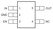
There are no other good reasons to use this pinout, other than that it has been used on previous boards.
It’s fine to use other packages that have a thermal pad or in general better thermal performance. Thermal performance of SOT23 package is relatively poor, but good enough for low currents.
Recommended voltage regulators below are just some that meet the requirements. There are probably cheaper and better performing regulators available.
Voltage regulator for microcontroller
Requirements
-
Input: 5V from USB.
-
Output: 3.3V, >200mA
-
For powering the microcontroller, encoders, isolators.
Isolators
Requirements
-
Should electrically isolate motors' battery from computer’s battery to avoid short circuits on the motor’s side damaging the computer.
-
Signals between the microcontroller and motor drivers should go through isolator(s).
-
Needs to work with 3.3V and 5V.
Encoder connectors
Programmer connector
Reverse voltage protection
Requirements
-
For avoiding reverse voltage damaging the components.
-
Should be connected between positive supply instead of ground to avoid having different ground potentials.
-
Simple and efficient solution is to use P-channel MOSFET.
-
MOSFET’s drain-source and gate-source rated voltages should be higher than battery voltage.
-
If battery voltage is higher than gate-source voltage, then zener diode can be used to clamp the gate voltage, and a resistor can be used to limit current through zener diode.
-
LEDs
Requirements
-
LEDs can be connected to microcontroller and used in firmware to indicate that something is working.
-
LEDs can also be connected to voltage regulator output to indicate that the board has power.
-
LED’s brightness is controlled with current. The simplest way to limit current is to use resistor in series with the LED.
-
LED’s current can be calculated with the following equation: , where VF is LED’s forward voltage. VF can be found in the LED’s datasheet.