Mechanics checklist
- General
- All sketches have to be fully defined
- Milled parts have to be modeled based on the material used for milling
- Milled parts should be modeled so they’re millable from one side
- Check interference between parts
- Make robot parts affixable without adhesives or pressure fit
- Make bolts and parts accessible
- Make bolt holes and their responses correctly dimensioned
- Make inside corners with dogbones
- Add models of components to the robot model
- Verify that the models you are using for the robot have same dimensions in real life
- Think about cables and wiring
- Make sure that batteries don’t move horizontally
- Round out sharp outside corners
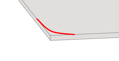
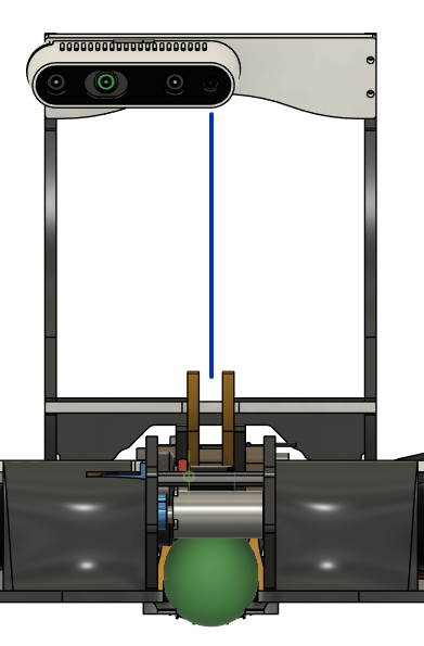
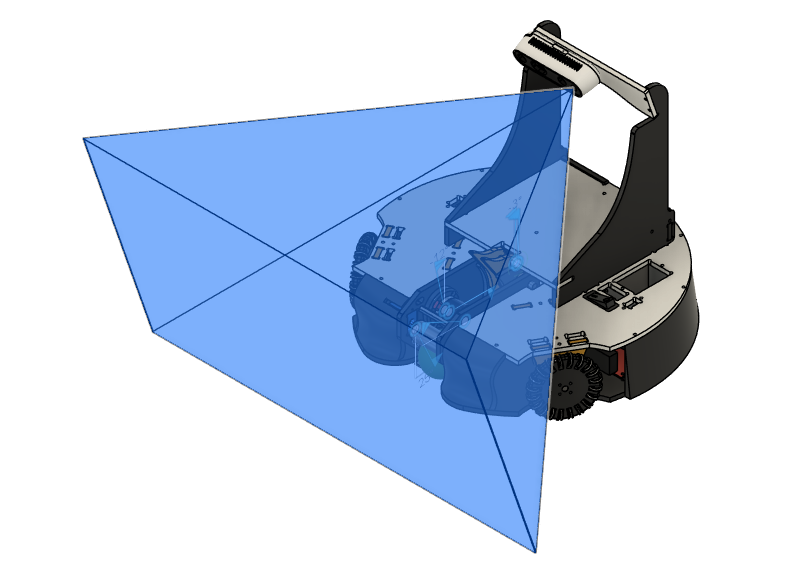
- Camera
- Thrower
General
Milled parts have to be modeled based on the material used for milling
Do not use nominal material measurements.
For example, do not model parts as if they are milled from 5mm thick material
when the material is actually 4,8mm.
Milled parts should be modeled so they’re millable from one side
Milled parts should be modeled so their features are millable from one side.
Milling from two sides is a time-consuming process.
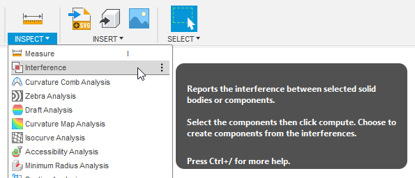
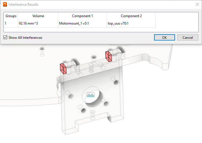
Check interference between parts
Use the Interference tool to check if any parts are misaligned.
The volume between two interfering parts will be shown.
If you have models that have many internal parts, e.g. computer or camera,
use only their frames for checking interference.
Make robot parts affixable without adhesives or pressure fit
In almost all cases, parts should be affixed using bolts.
Make bolts and parts accessible
Bolts used for affixing parts to the chassis should be accessible.
When designing parts that are attached together, you should think about how
the components are positioned and assembled together.
"How many parts do I need to disassemble to access this specific component?"
"Would this new part cover up a bolt that I would constantly need to access?"
Make bolt holes and their responses correctly dimensioned
When a bolt goes through multiple parts, only the last part should have a
threaded hole.
Having the correct responses modeled will be a good reference when making
threaded holes for the physical parts.
Make inside corners with dogbones
When milling, sharp inside corners are impossible to be milled due to the
radius of the tool. This will cause the corners to be rounded, and this can
cause unplanned changes to the model.
Use dogbones when something needs to properly fit into a rectangular hole.
If a hole is used for passing cables or wires through, dogbones are not needed
and only rounded corners can be used.
Add models of components to the robot model
Having models of all main components, i.e. voltage regulator, mainboard,
switches, batteries, etc., will give you a better visual of how everything will
fit inside.
These models should also have features such as mounting holes and positions of
the cables running from the component.
Verify that the models you are using for the robot have same dimensions in real life
Verify the actual dimensions of the models you are using in your robot.
Verify the dimensions of mounting holes on the components.
Think about cables and wiring
Cables and wiring take up some space, consider their path when they route
between components.
Cable plugs take up a lot of space, leave room for them to be pluggable-
unpluggable.